Bode Plot Of Rlc Circuit
Rlc parallel bode plots circuit case shows pages preview Bode plot of the equivalent circuit of an impedance cell containing Rlc circuit plot bode has series solved transfer function magnitude transcribed problem text been show
Series RLC Circuit Analysis - Electronics-Lab.com
Rlc lab Engr 301 lab 1 Series rlc circuit analysis
Signal processing
Bode rlc circuitRlc circuit filter bode plot consider second below order figure Bode plotter mode improvement suggestionSolved the objective of this experiment is analze the.
Bode plotBode circuit frequency response plot composition rc rlc series parallel filter arrangement wonder terms kind has stack Bode plot rlc filter bandpass parallel q5 solved below represents transcribed problem text been show hasAnalyzing the response of an rlc circuit.
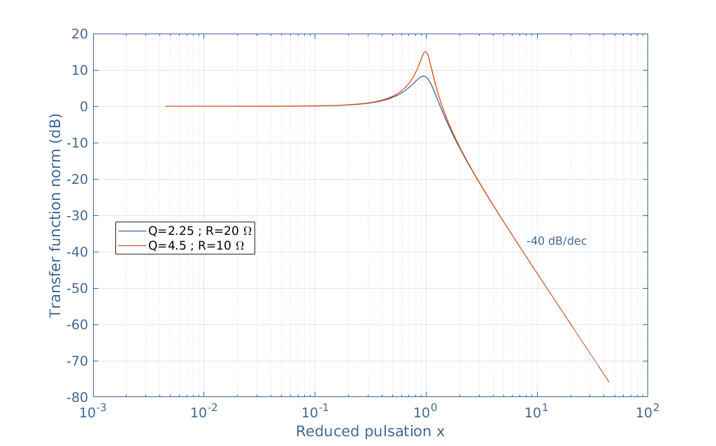
![Solved The objective of this experiment is analze the | Chegg.com](https://i2.wp.com/media.cheggcdn.com/media/50f/50f983fb-45db-48c3-b9d1-63d562bc2104/php65pRMq.png)
Parallel rlc bode
Bode nyquist plots 100ω parallelBode plots parallel rlc 18 nyquist a) and bode plots b) c) for a series rc circuit with rBode rlc values fig different response plots lab1.
Solved a series rlc circuit has the above bode magnitudeRlc circuit response filter frequency matlab mathworks analyzing control help resistor narrowly tuned gives value Bode rlc transcribedBode plotter suggestion simulated.
![Bode plot of the equivalent circuit of an impedance cell containing](https://i2.wp.com/www.researchgate.net/profile/Hongshen-Ma/publication/260636619/figure/fig6/AS:667044404011009@1536047187199/Bode-plot-of-the-equivalent-circuit-of-an-impedance-cell-containing-mobile-charge_Q640.jpg)
Bode plots parallel rlc
Signal processingBode circuit impedance equivalent containing Bode rlc parallelSolved q5: the bode plot below represents a parallel rlc.
.
![Analyzing the Response of an RLC Circuit - MATLAB & Simulink](https://i2.wp.com/it.mathworks.com/help/examples/control/win64/rlcdemo_02.png)
![Series RLC Circuit Analysis - Electronics-Lab.com](https://i2.wp.com/www.electronics-lab.com/wp-content/uploads/2020/02/figmatlab3.png)
![signal processing - Bode plot parallel RLC circuit - Mathematics Stack](https://i2.wp.com/i.stack.imgur.com/kEJ1O.gif)
![Solved Q5: The bode plot below represents a parallel RLC | Chegg.com](https://i2.wp.com/media.cheggcdn.com/study/516/s700x676/516838a1-f994-4050-8985-0c4c0e0057ef/image.png)
![18 Nyquist a) and Bode plots b) c) for a series RC circuit with R](https://i2.wp.com/www.researchgate.net/profile/Francesca-Leonardi-3/publication/275023426/figure/fig23/AS:613948898435087@1523388232376/Nyquist-a-and-Bode-plots-b-c-for-a-series-RC-circuit-with-R-100O-and-S-1mF-Nyquist.png)
![Solved A series RLC circuit has the above Bode magnitude | Chegg.com](https://i2.wp.com/d2vlcm61l7u1fs.cloudfront.net/media/da4/da4d6e56-f026-4059-82dd-745bfd55b2e5/phpCI1tKq.png)
![analog - Finiding composition of circuit from frequency response and](https://i2.wp.com/i.stack.imgur.com/85DDI.png)
![Bode Plotter Mode improvement suggestion - PC Oscilloscopes and](https://i2.wp.com/i60.servimg.com/u/f60/11/80/59/89/normal10.png)
![ENGR 301 Lab 1](https://i2.wp.com/www.tinmancp.com/engr301/lab1/lab1_files/fig3.gif)